Authors:
(1) Taha Laroussi, Laboratoire d’Hydrodynamique (LadHyX), CNRS, Ecole Polytechnique, Institut Polytechnique de Paris, 91120 Palaiseau, France;
(2) Mojtaba Jarrahi, Universit´e Paris-Saclay, CNRS, FAST, 91405 Orsay, France;
(3) Gabriel Amselem, Laboratoire d’Hydrodynamique (LadHyX), CNRS, Ecole Polytechnique, Institut Polytechnique de Paris, 91120 Palaiseau, France.
Table of Links
Discussion, Acknowledgements and References
II. METHODS
A. Culture preparation
C. reinhardtii strain CC-125 (Chlamydomonas Resource Center, University of Minnesota, MN, USA) were cultured on a solid medium prepared with TrisAcetate-Phosphate (Gibco™ TAP, ThermoFischer Scientific, France) and agar every 4 weeks, to keep the strain motile, responsive to light and prevent as much as possible the cells from sticking to the walls of the devices. For experiments, colonies of C. reinhardtii were picked from solid cultures and recultured in liquid TAP. The cultures were placed in an agitating incubator at 176 rpm, under a day/light cycle of 14h/10h with an illuminance of 60 µmol · m−2 · s −1 and at a fixed temperature of 22◦C. The cells reached maximum motile cell density within 3 days [16], after which a solution of swimming C. reinhardtii was obtained.
Before being used for experiments, the cultures underwent a series of centrifugation steps. This enabled to concentrate the algal solution, get rid of low-motility and dead algae, and of cellular debris. First, 45 mL of the liquid culture were centrifuged at 1057g for 10 minutes. Then, 39 mL of the supernatant was removed, and the bottom 6 mL were centrifuged at 73g for 2 minutes. The supernatant, containing the motile cells, was kept and centrifuged again at 285g for 5 minutes. The amount of supernatant was adjusted to obtain the desired algae final concentration.
B. Experimental setup
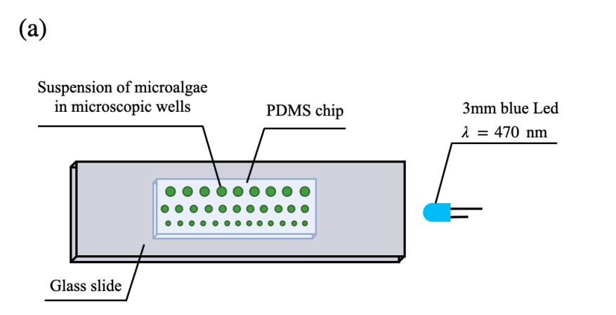
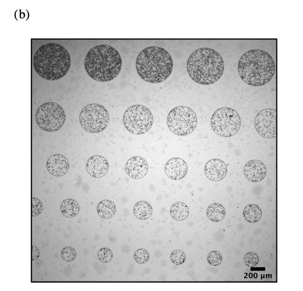
An array of shallow cylindrical wells was made in polydimethylsiloxane (PDMS, Dow-Corning Sylgard 184), using standard soft lithography techniques [17]. The wells had a depth of 32 µm and diameters ranging from 200 µm to 500 µm. The PDMS was rendered hydrophilic by plasma cleaning. Then, a drop of ≈ 10 µL of the algal solution was deposited on the PDMS. The device was closed with a plasma-activated glass slide by applying gentle pressure.
The trapped algae were observed under a Nikon TI microscope, using a 4x objective. Images were recorded at 10 fps with a CMOS camera (Hamamatsu ORCAFlash4.0 LT, Hamamatsu Photonics, France). A longpass red filter with a 645 nm cut-on wavelength (Newport RG645) was placed between the microscope’s light source and the microwells. A 3 mm blue LED with a wavelength λ = 470 nm and a light intensity of 7000 mcd (Plan`ete Leds, France) was placed on the microscope’s plate, approximately 2 cm away from the microfluidic chip, on the same plane. The LED operating voltage range was between 2.4 V and 3.2 V and its operating current was 20 mA. The light intensity was tuned by varying the applied voltage. An illustration of the setup is shown in Fig. 1.
The algae concentration ϕ was determined in each well from images captured at the beginning of the experiments, before exposition to a light stimulus. Initially, the algae swam randomly and were distributed homogeneously in each well. They were identified by thresholding the images, and the total area they occupied in each well was determined. The concentration in algae was then defined as the fraction of surface area occupied by the algae in the well.
C. Measuring the local light intensity
We estimated the local light intensity inside a well using the number of photons reaching the sensor of the


camera. First, we determined the camera offset value by blocking off all the light to the camera and taking a 16-bit image. The spatial average intensity in grey value of all the pixels in the image was the camera’s offset. Then, a 16-bit setup image of the sample was taken at the current experimental condition, with the light of the microscope turned off and the blue LED light on. The camera offset value was then subtracted from each pixel in the setup image. The grey values were first converted to number of electrons by dividing each pixel in the image by the conversion gain of the camera. The electrons were converted to photons by dividing the number of electrons from each pixel by the quantum efficiency (QE) of the sensor at λ = 470 nm. Last, the local light intensity inside a well was computed as the average number of photons within the well.
This paper is available on arxiv under CC 4.0 license.

